Original post at Twitter here
So I had been meaning for a while to do a little commentary on the Tesla 4680 teardown organised by The Limiting Factor, partly because teardown is part of my day job… so here come some observations, starting with the “part 1” video:
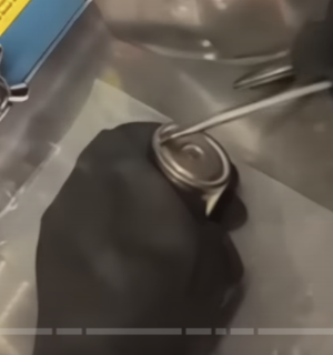
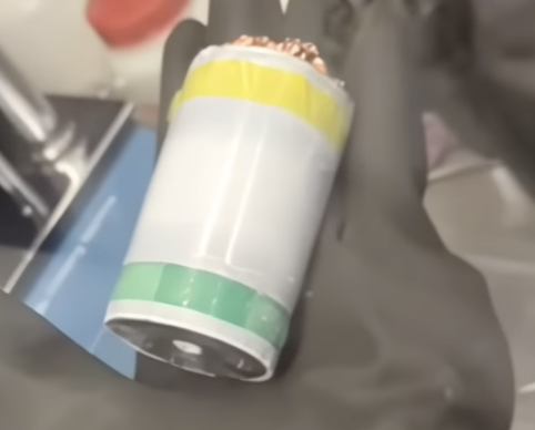
4:27 - Cell voltage is pretty low, 0.14 V - which is way below the usual 0% SoC. The cell is dented, but the voltage is not zero, so tells me it’s not short circuited (at least at the time of teardown) - guessing it was discarded from the line and hasn’t gone through formation
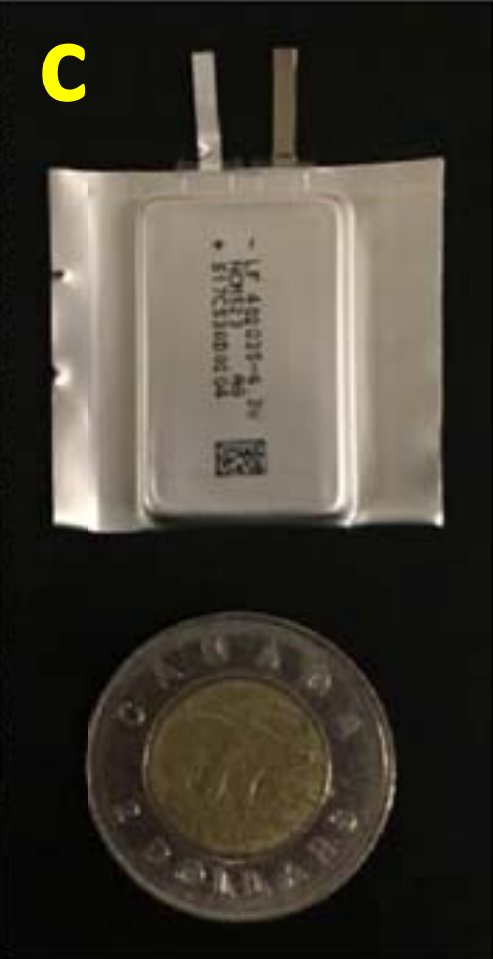
Interesting new features about this format: large areas to connect both electrodes on the top of the cell (centre: +ve, outside: -ve). The bottom (where I guess the can is crimped closed) is insulated from the rest of the can and has (I expect) a safety vent.
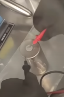
Measuring the OCV at the terminals
Insulated bottom of the cell can
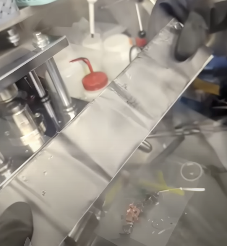
7:31 - already this cell looks like hard work to get into! Opening cells with manual tools is hard, and the glove box doesn’t make it easier, with high risk of short-circuit, cutting gloves etc. At least in this case the cell is totally dead.
In this situation I would have probably tried to go for a pipe cutter to open the cell (and an x-ray before can help show where things are). We know the jelly roll is wrapped in separator as well, so I think with some care that would have been faster and easier.
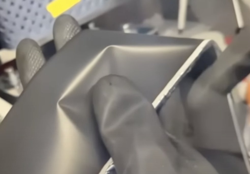
13:48 - finally the bottom cap comes off and can see the copper anode. Still a bit curious as to how the cap is insulated. I guess it is done so the cell can be connected to a cooling plate without shorting all the cells, was wondering if the cap coated or something…
I’m not that closely following pack teardown efforts but guessing the cells are bottom (and side?)-cooled, and the thermal conductivity is best going towards the bottom of the cell. Not that knowledgeable on these things though. Not unusual that the rest of the cell can is connected to the -ve electrode though, this is normal with cylindrical (and with aluminum-can prismatics, the can is normally connected to positive).
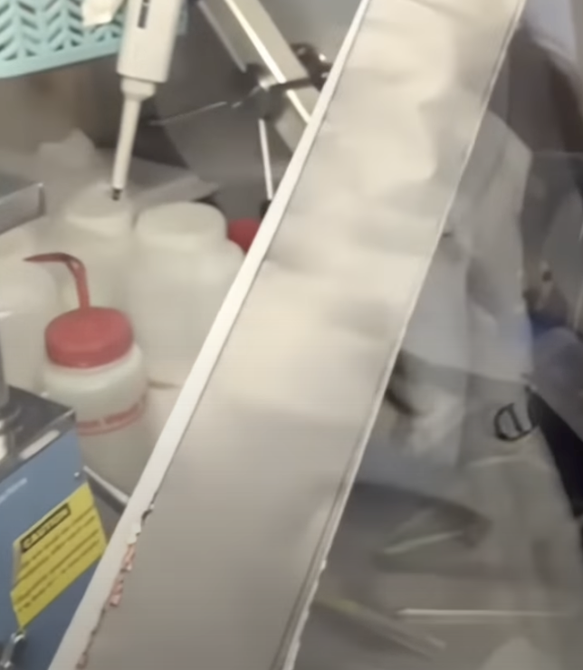
Arbitrary time for a tip for any lab doing interesting stuff in a glove box: buy a camera to have in the glove box! Makes for much better pictures than taking photos through the glass…
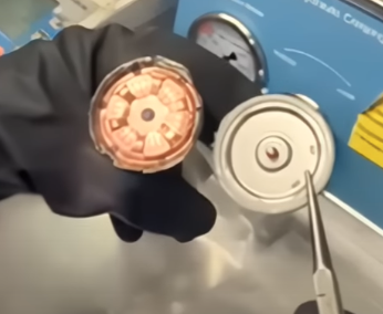
21:48 - was curious to learn before how the connection of the tabless electrode would be made because I figured this would be both tricky and important. Seems this ‘flower’ of Cu is welded to the jelly roll (presumably before going into the can)…
…and then a flower-to-can connection is made later? The weld, I imagine, is crucial - need it to avoid a high contact resistance to the can, and must avoid bringing contaminant particles into the cell which could create a short circuit later.
28:07 - finally getting the jelly roll out is pretty satisfying, even to watch! And probably just as well it’s not an aged cell as with a bit of swelling, would have had to cut away more of the can.
30:46 - kinda interesting that the separator comes all the way down to the tab edge of the +ve electrode but the -ve electrode sticks out of the end. Guessing that is so the -ve can make a bigger contact to the sides at the bottom?
33:01 - also interesting that the first couple of turns do not have the ‘tabless’ tabs sticking out of the top. Looks maybe 40-50 cm or so? And would have a first guess the whole roll is ~3.5 m fully unwound so it seems a fairly big portion.
40:43 - Pretty nice looking electrodes - looks homogeneous, ‘shiny’, decent adhesion, no cracking etc. Seems also that there’s a relatively large amount of separator sticking out either side of the electrode too?
Homogeneous-looking electrodes
42:43 - Weikang also notes that the electrodes and separator look very clean, hasn’t been cycled and probably not gone through formation, as I guessed earlier. Probably would look the same even if formed and just a few gentle cycles, I would think.
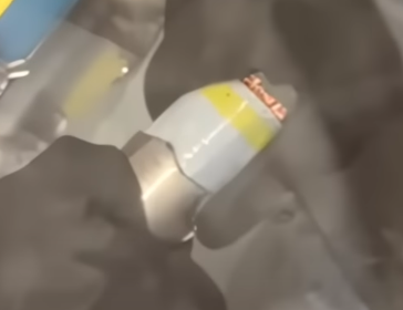
43:23 - Might have mistaken it for separator earlier but interesting to note this coating - maybe aluminium oxide? - along the top edge of the positive electrode. I believe there are other manufacturers doing this too, and expect it’s for safety reasons.
I guessed ~3.5 m and the positive is estimated at about 3.3 m, and 70 mm wide - assuming the capacity is at least 25 Ah that would put the electrode capacity >5 mAh/cm2, which is pretty thick! Didn’t spot it in the video but was curious about the separator. It’s common now to have an aluminium oxide or boehmite coating generally on the +ve-facing side. Can sort of see this as it tends to appear matte, and the uncoated side shiny, but can’t see in the video.
57:07 - Didn’t know up to this point that 4.5 µm Cu foil was in production! That’s crazy thin. There’s also perhaps a relevant trade off here. Thinner Cu means better energy density, but less ability to conduct heat from the electrodes away through the Cu.
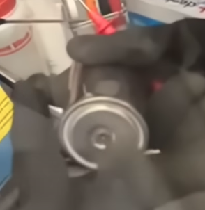
1:07:16 - what kind of steel is the can made of? I would guess here Ni-plated steel, as it is quite commonly used for cylindrical and coin cells for good strength, corrosion resistance etc. But can’t tell just by looking…
1:08:00 - ~600 µm thick steel is v. thick! That’s 4-5x thicker than is typical for a smaller (2170/18650) cylindrical cell. It’s much more in line with the thickness of Al in prismatic cans, but there they are much lighter. So the can has got to be relatively heavy here
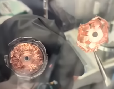
1:11:17 The different directions of the ‘petals’ in the ‘flowers’ is interesting.
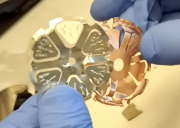
Current collector "petals"
Wonder if there is a reason for this besides accommodating different size central parts for each of them (the centre of the +ve is connected to the ‘button’ on the top of the cell, but the edge contact to the can on the -ve is on the side).
1:11:39 - Is the can so thick because it is structural? I’m not sure if this is the case or if it is just to manage swelling, but I do wonder why the can needs to be 4-5x usual thickness if it’s just to manage swelling alone (and sacrifice energy density in the process)
Ok, reached the end! Nice to get a proper look at the inside of the cell but what I’m most interested in is the specs. And since I took so long to make this thread there’s already an initial video on that too!
1:26 - A note that this cell is from about 6 mo ago and is not a production version, so some things may differ. Might be true, but if the cell is that recent then it is probably “C-sample” or similar and I doubt it would differ in any significant way from a production cell. Changes to chemistry, thicknesses, production methods etc are very risky to change at this stage even if Tesla are supplying to themselves.
2:30 - I admit I was quite surprised to see the evidence for the dry coating process here, and only on the anode too It’s the first time I’ve heard of it in a production cell. Couldn’t tell you why it’s used on one but not the other, but they are quite different materials…
3:12 - I was also surprised to see NMC 811 rather than NCA as in their 2170 cells. Rather than being less Co, it’s actually almost certainly a bit more than they used to use…!
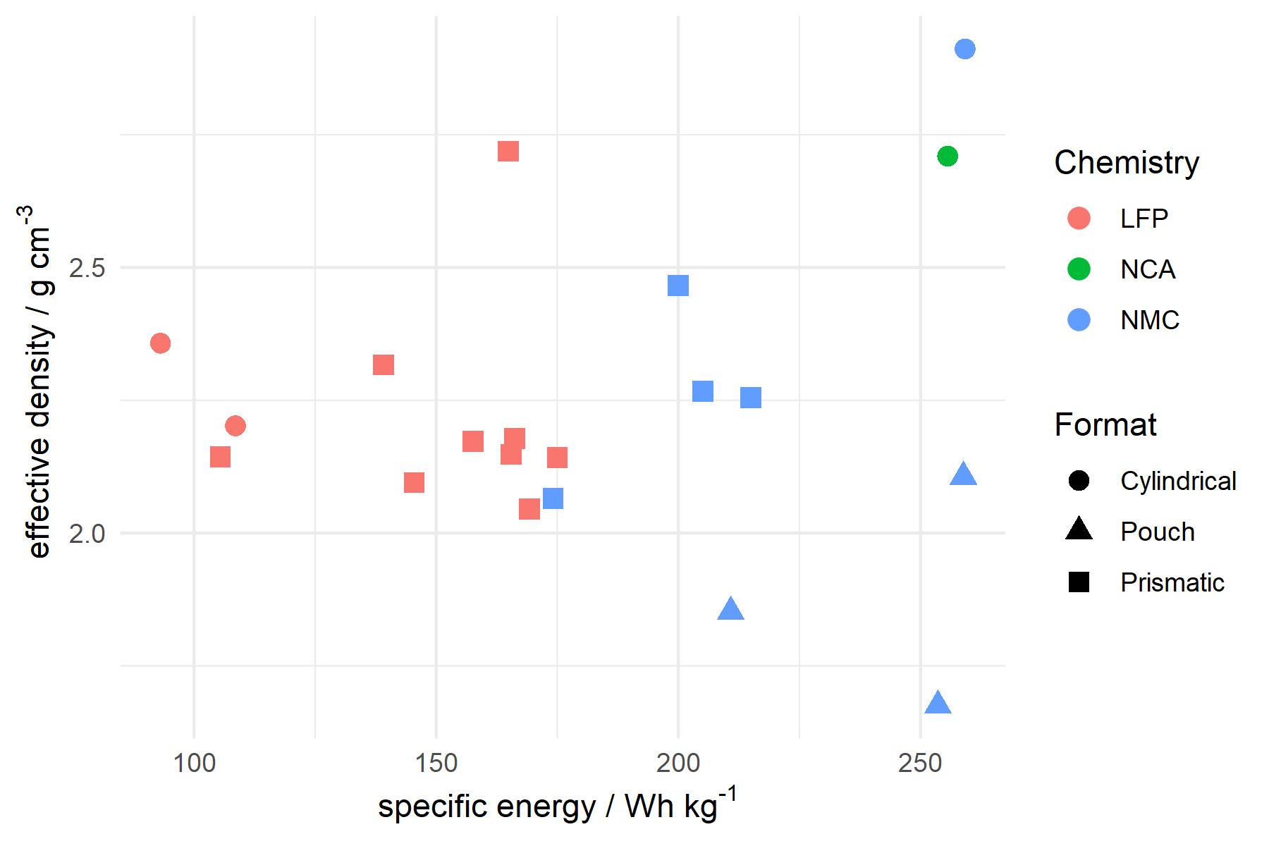
3:30 OK, onto energy density. I suspect there might be some overestimation here… and perhaps bias from an expectation that the cell should have an exceptionally high energy density? Will dig into this shortly…
6:08 - Surprise #3, no Si in the anode, which @limitingthe says is a “deliberate choice” - and it certainly is, since this is against what I expected the trend in passenger EVs to be, so it should tell us something.
8:11 - The conclusion is that the two handicaps of a very thick can and no silicon are offset by thicker electrodes to beat the energy density of the 2170. I’m not sure this is fully correct, but the later points of pack integration and manufacturability are important.
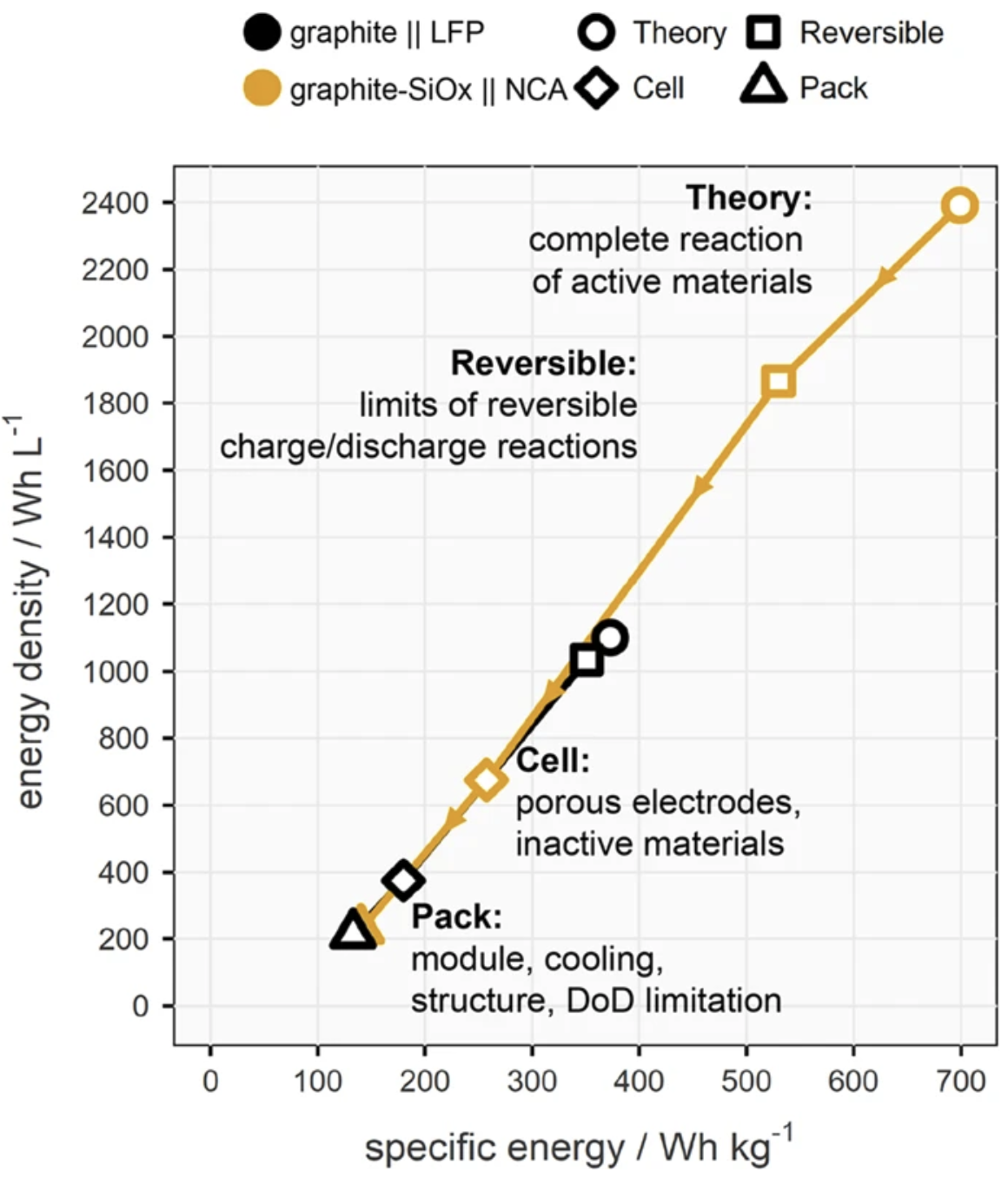
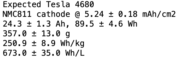
So to dig into details here, I dusted off my cell model and tried to find something representative based on the data available so far. This is what I get: 24-25 Ah and ~250 Wh/kg, less than I expected and less than UCSD calculated so far.
A few numbers are best guesses, but otherwise thicknesses, jelly roll length etc roughly agree with measurements. There’s a few reasons why I think my numbers might be a bit closer to reality.
- I don’t expect thicker electrodes offset much the thick can and the lack of Si. The 2170 cell +ve electrodes are ~4.5 mAh/cm2. Going up to ~5.2-5.3 (my estimate) is about a 2-3% energy bump. The can thickness is a >10% penalty and lack of Si not far behind.
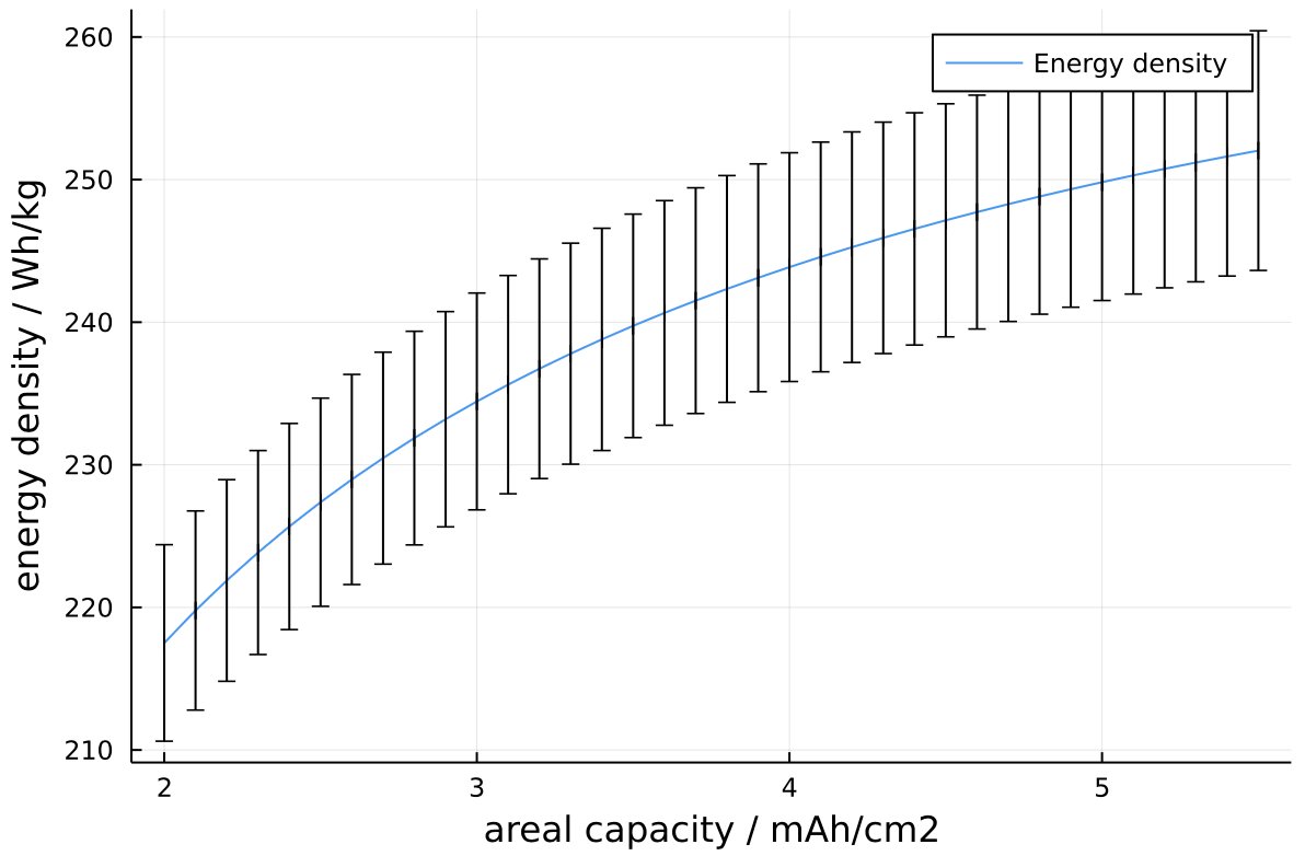
Energy density vs areal capacity
- Estimating cell-level capacity from anode areal capacity will overestimate slightly because of balancing and first-cycle losses. (Also the voltage is a tiny bit overestimated, nominal for NMC811/Gr should be ~3.68 V).
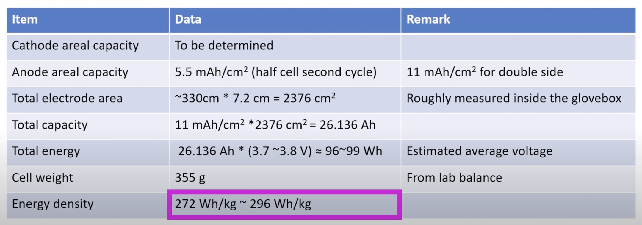
Table of material level properties
A difficulty is, if this cell hasn’t gone through formation, we can’t account for first cycle losses accurately, because there haven’t been any. As an example, I know from my own data that in Tesla’s 2170 cell, the actual cyclable mAh/cm2 is a bit <15% of the anode mAh/cm2 (I have been conservative with my model and assumed relatively close balancing and low initial losses, so my effective n/p ratio comes out to be ~1.08).
So why does it make sense for the energy density to be lower, you might ask? Well, I think the answer is a) it is what it needs to be, b) cycle life (maybe) and c) (probably mostly) cost optimisation.
First
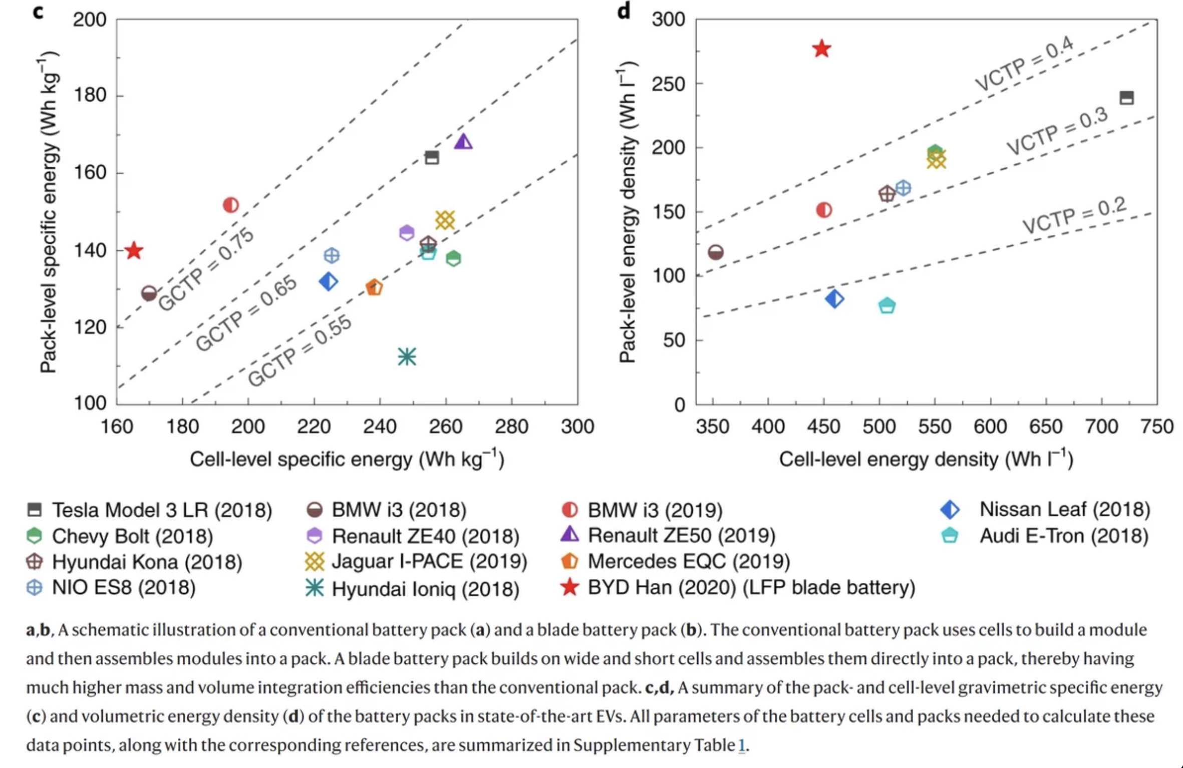
@limiting_the is right to point out that it’s part of a ‘structural’ pack with better integration efficiency so that makes up for any sacrifices on the cell level (which by my numbers is still on par with the 2170 cell, which is also ~250 Wh/kg). Second, I first assumed the exclusion of Si might be for cycle life reasons - Si does come with a cycle life penalty, and maybe the larger form factor does also? Though I am mainly wondering out loud on this point.
I think the bigger aspect (incl. the thicker electrodes) is probably cost optimisation. Going up in mAh/cm2 bumps energy by 2-3% but decreases the length of the electrode that needs to be coated by almost 15%, and this saves some cost.
Jelly roll length vs areal capacity
Adding Si would make the negative electrode thinner, but also make the length of jelly roll per cell longer again (also by ~15% by my estimation). Don’t have much feel for how much this affects cost but I’m assuming it is not negligible…
So to wrap up, because this thread is already much too long, certainly at first glance Tesla’s 4680 looks like a very high quality cell, with some cutting edge production methods. We’ll have to wait and see about performance later, but my guess is the energy density will come in a bit lower than many expect. My numbers might be a bit off, but 250 Wh/kg is also about right for large format prismatics with the same chemistry so to me it fits.
I would be quite surprised if the production version comes in at >270 Wh/kg unless something has changed significantly from this version. But it doesn’t matter - even at 250 Wh/kg cell level I’m sure the pack integration means the Wh/kg on system level beats the 2170 pack. And I’m guessing it doesn’t compromise from the 2170 on any other metric, e.g. charging time. Boosting performance further can come later, but my guess is the main focus now has been cost optimisation, which is what Tesla made a big fuss about on battery day anyway.
]]>